


Facility Vulnerability with VISAC |
|
|
|
|
|
VISAC uses several types of models to make it calculations. The logic model describes how the different aspects of facility operation are related back to the individual critical components. The geometry model describes the entire plant geometry in terms of solid shapes, such as cylinders and rectangular parallelpipeds. The MBLM model contains inventories of haxardous materials for each critical component.
All of the models used by VISAC can be displayedby the user.
The logic models tell VISAC how to propogate damage from the basic events, through the plant safety systems to a final consequence for each aspect of the plant. This is done using five model parts:
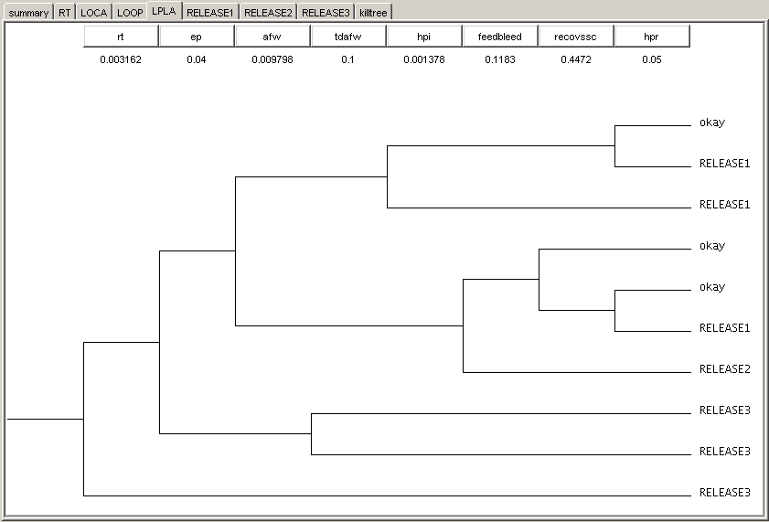
Figure 2. An event tree from the west560 plant logic model. |
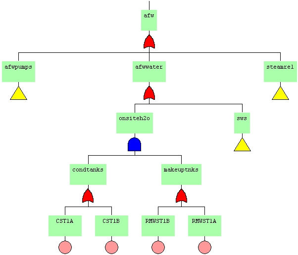
Figure 3. A fault tree from the west560 plant logic model. |
|
The most important of these the fault tree/event tree model. Using EFTed in its View mode, users can see how the individual basic events (which correspond to the geometric critical components) are connected using "and" and "or" gates to form fault trees for plant subsystems. These fault trees are then connected together using an event tree. Paths through an event tree are determined by which fault trees have been failed due to basic event damage. Each sequence in an event tree ends with with either another event tree or a consequence. The other parts of the logic model each have their own viewer accessable from VISAC by either the menu bar or the expandable tree structure on the left hand side of the VISAC window. The analysis parameters group several event trees together to describe an aspect. The calculation parameters tell EFcalc how do perform the calculations. Gate downtimes are used to supercede downtimes calculated by EFcalc for certain gates where the system downtime is known. Accident definitions list which systems are failed for each of the defined accidents. The logic models are stored as a set of ASCII text files. |
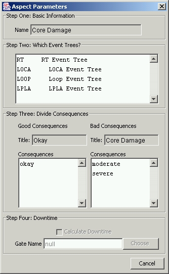
Figure 4. Setting up an aspect. |
|
VISAC's main interface for the geometry model is the Edificio editor. When using Edificio to view the facility geometry, each floor of each building can be displayed along with information about all of the critical components on that floor. Minimum and maximum blast overpressure fragilities are also listed for each critical component. The blast overpressure fragility values can also be viewed directly from VISAC through either the menu bar or the expandable tree structure. This separate viewer allows users to see all of the fragility information for all the components at once. The way these fragilities are used by the QuickBlast package is as follows: for overpressures less than the minimum, no damage to the component occurs. For overpressures greater than the maximum, the critical component is considered failed with a probability of 100%. For overpressures in between, the failure probability is a linear function with overpressure. The last part of the geometry model that the user can view is the link between the geometry critcal components and logical basic events. Any number of critical components can be mapped to a basic event. A given critical component can be mapped to exactly one basic event. This link is how damage calculated by QuickBlast using the geoemtry model is transfered to the logic model to evaluate the event/fault trees. |
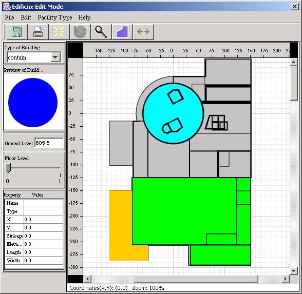
Figure 5. Edificio, the geometry editor, shown with a portion of the west560 plant. |
The geometry model is stored as a set of ASCII text files, one per building, in a specific format. These files are then referenced by another ASCII text file (the *.bil file) to place the buildings onto a common canvas.
The base MBLM model descibes the different rooms and how they are connected together. This information is displayed using MblmGui. The plant inventory is a list materials that each basic event contains, and which room it is located. This information is used to build an input deck for the MBLM code, which can calculate material transport inside buildings. The MBLM model is not used for all types of facilities, only for those facilities where releases are a concern.
The MBLM model is stored as a set of two ASCII text files, one for the base MBLM connectivity model and one for the inventory.
Oak Ridge National Laboratory, 2004